WeldingWeb - Welding Community for pros and enthusiasts banner

ESAB A10-160K Circuit Board Problem

14K views 41 replies 4 participants last post by  Bluewelders  
#1 ·
Hello everyone,

Glad to be a part of this community.

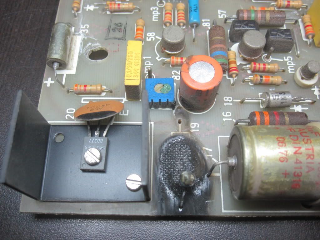
I picked up an old ESAB A10-160K with bead, spot and stitch welding capabilities for about 60 bucks. This machine is awesome; small, no fan (quiet), dead simple to use. I used on on 208V for a while but decided to run it on 460V as I installed a 460V circuit in the shop. Anyway, upon switching it over to 460, I forgot to change the control transformer wire and subsequently burned up a resistor on the board. Fortunately, the control transformer (42V) is fine. I want to replace the resistor on the board but it's fried to pieces so I can't tell what value it is. If anyone out there knows what value it is or could send me a photo of their board, that would be amazing. It is resistor #19, labeled on the board, right next to the big capacitor.

Thanks,
brokespokes
 
#3 ·
If the resistor is the one labeled 19, than it would have been the current limiter for the 24v regulator circuit.
I would be worried that the transistor labeled 20,and the zener labeled 18 may be damaged.
Does the transistor labeled 20 have any part numbers on it ?
 
#4 ·
Great info, thanks for the feedback Bluewelder. It looks like the transistor and zener are fine but hard to tell. The transistor is labeled SS ATES BD377. I have a hard time making out the first two characters though. It may be SG. The zener is labeled SILE 1N3029. Also, I believe that component #19 is a resistor but not entirely sure. On a good note, I checked the control transformer today and it's fine.

Thanks again
 
#5 ·
The 1N3029 is a 24v 1watt zener diode,which was to be expected.
The transistor is only good to about 60v and you may have put 80 or so on it.
If you could measure the length and diameter of the resistor we could guess the wattage.
Does the BD377 transistor have a heat sink.
The BD377 is a 25watt 2amp transistor,we should be able to make a guess as to the value of the resistor.
But a lot would depend on the wattage/size of the resistor and if the transistor is heatsinked.
 
#6 ·
Nice, thanks for the quick response. Judging from three other resistors on the board similar in size and the outline drawn on the board the dimensions are around .729 inches in length and .240 in diameter. The transistor is heat sinked. Once I get home later, I can snap a pick of the board and post it up.
 
#8 ·
My buddy just showed up with a camera. Also charred a capacitor but I have an extra one of those. Check it out:

Image

Image

Image
 
#12 ·
I double checked everything. Not sure which is the tail end of the zener so I checked both ends, both ways. From the side of the zener with the label 18 to mp1 I got 16 Ohms both ways. From the other end to mp1, both ways: 49 Ohms. The zener itself reads 33 Ohms both ways, for sure.

Thanks for the help Blue, much appreciated.
 
#13 ·
The resistance reading is very low, I would suspect that some of the downstream transistors or zeners have gone short because of the over voltage.
It is labor intensive, but the only way to tell what is what, would be to pull the transistors and zeners and test or replace them.
 
#14 ·
Yeah, I was afraid of that. Well, I will start on doing that but my question is which way is downstream (and is anything fried upstream)? I am guessing from the diagram that you mean # 86, 87, 55, 60, 58. That still leaves the question of the value of the burned out resistor too I guess. I will start on it this week. From the data sheet on that diode, I am guessing it should be around 750 Ohms. Is this correct? I guess I should compare all components to their respective sheets. I haven't really done this before, but am looking forward to working on the problem. Can you suggest a good plan of attack?
 
#15 ·
The first thing I would do is pull the 18 and 20,and check the voltage across capacitor part 17,with the control transformer powered up.
if that has 60 v that part is ok.
Then with the power off I would check the resistance again, from the ends of capacitor 21 to mp1.
 
#16 ·
Sounds good, I will do that today. I can see capacitor 21 on the circuit diagram but not on the board? (I don't have the board in front of me at the moment, just looking at the pictures). I am guessing it's the one I charred. I can trace it I guess once I get the board in front of me.

Thanks
 
#17 ·
Blue,

So I pulled it all apart and tested everything. Across #17, I am getting 73V both ways (have it hooked up to 460V mains).

Still 33 Ohms across the zener both ways (it's actually a 1N3029B, didn't see the B before)

The transistor measures 27 ohms both ways from b to c and 16 ohms both ways from b to e. Putting it in my transistor tester on my multimeter (hFE) I am not getting any reading.

On capacitor 21 to mp1, one way I am getting 119 KOhms, the other way 78KOhms. I figured 21 is the yellow capacitor, not the one I was thinking.
 
#18 ·
That is 73v DC I hope.
Sounds like the zener and transistor are toast.
The good news is,them going short and burning out the resistor, may have saved the other parts.
So I guess if you grab a new zener and transistor,I could ballbark a resistor that would be enough to test it.
 
#19 ·
Ha!, yeah 73V DC. Good news. I will order up those parts tomorrow. I got a line on the BD377 on ebay but will check in to the local electronics shack tomorrow to see what they got on hand. Thanks for the help again, will get back when I get some parts together.
 
#21 ·